


Basic electrochemical H-cell setup (redox.me)
This is a stationary solution double compartment electrochemical H-Cell for measurements of electrodes in a form of:
a) rod/disc (6 mm dia.),
b) thin film deposited on a flat substrate (using a wire clip) and
c) membrane (using a wire clip).
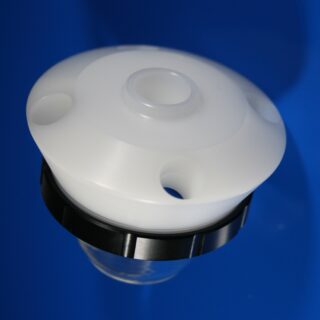
The working, counter and reference electrodes are mounted in a top casing either in 2-, or 3-electrode setup. The counter electrode is placed in a compartment separated from the other electrodes by ion-exchange membrane (19 mm to 25 mm dia.), so the electrochemical products appearing at working and counter electrode do not affect the opposite electrode. The counter electrode compartment is equipped with a separate inlet and outlet for easy filling with an electrolyte and evacuation of gaseous products. It can accommodate standard Metal Wire Auxiliary Electrode as well as square shape electrodes with sizes up to 25 mm x 25 mm. The cell elements are constructed with materials that are inert to the sample (glass and PEEK). It well fits aqueous (FKM/EPDM O-Rings) and organic solvent (FFKM O-Rings) electrolyte requirements. The construction is gas-tight and can be used when the removal and exclusion of contaminants such as oxygen and water is required by bubbling of an inert gas through the electrolyte. After removal of the counter electrode glass compartment, the cell gets the functionality of a Basic Electrochemical Cell – BEC 50 mL.
The cell chamber is available in several material variants here.
Application note:
The reference electrode tip and working disk electrode tip should be placed in the middle of the membrane. This will ensure a low potential drop throughout the electrolyte solution for low-current experiment. Various auxiliary electrodes are suitable for this cell including metal wire and metal foil/mesh/foam electrodes as well as graphite rod. The bubbling of gas through the solution must be stopped prior to experiment.
Specification:
minimum electrolyte volume in WE compartment: 22 mL
minimum electrolyte volume in CE compartment: 6 mL
maximum electrolyte volume: 40 mL
minimum membrane diameter: 19 mm
maximum membrane diameter: 25 mm
maximum membrane thickness: 0.5 mm
electrode plug diameter: 6 mm
number of electrode slots: 3
Intrastat data:
HS Code: 90309000
Country of Origin: Sweden
NET weight: 200 g
Setup includes:
1 x BE H-Cell 50 mL – Basic Electrochemical H-Cell 50 mL
1 x Metal Wire Auxiliary Electrode – 50HX15 0.6/250 mm (Platinum)
1 x Reference electrode (Ag/AgCl, or Ag/Ag+)
1 x Glassy Carbon disk electrode – 2 mm dia.
1 x Plug with silicone rubber septum and set of Tantalum wire clips (set of 10)
Select configuration
Variant: water based / organic electrolyte
Related products
-

Standard electrochemical cell setup (redox.me)
Read moreThis is a stationary solution standard electrochemical (electrolytic) cell for measurements of electrodes in a form of:
a) rod/disc (6 mm dia.),
b) thin film deposited on a flat substrate (using a sample holder) and
c) free-standing membrane (using the basic sample holder).
The working, counter, and reference electrodes are mounted in a top casing either in 2-, or 3-electrode setup. The cell has two spare ports for connection of e.g. thermometer, Clark electrode, pH meter electrode, or other 6 mm dia. electrode/probe.
The cell elements are constructed with materials that are inert to the sample (glass and PEEK). It well fits aqueous (EPDM O-Rings) and organic solvent (FFKM O-Rings) electrolyte requirements. The construction is gas-tight and can be used when the removal and exclusion of contaminants such as oxygen and water is required by bubbling of an inert gas through the electrolyte. The jacketed model is available here.
Application note
The reference electrode tip should be placed close to a working electrode center. This will ensure a low potential drop throughout the electrolyte solution for low-current experiment. Various auxiliary electrodes are suitable for this cell including metal wire and metal foil electrodes as well as graphite rod. The bubbling of gas through the solution must be stopped prior to experiment.Specification:
maximum electrolyte volume: 100, 150, 200, 250, 350, 500 or 1000 mL
electrode plug diameter: 6 mm
number of electrode ports: 5
vial material: borosilicate 3.3 glassIntrastat data:
HS Code: 90309000
Country of Origin: Sweden
NET weight: 200 g (100, 150 mL), 300 g (200, 250, 350 mL), 400 g (500 mL), 600 g (1000 mL) -
TC6 Electrochemical Glass Cell
Read moreBorosilicate glass cell serves for electrochemical measurements.
The analyzed solution can be thermostated by minithermostat MT1-1.
Cell openings are designed for electrochemical sensors connector KA1.C, classical electrodes WCEc, ACEc, RCEc and stirrer ST1, ST3 separately.
The device enables the measurement with inserted samples.
-

Three Electrode Battery Test Cell – compression controlled (redox.me)
Read moreThis cell is designed as high-quality alternative to Swagelok-type constructions for reproducible electrochemical measurements of battery and supercapacitor materials.
The cell consists of two main elements:
(i) the cell base with micrometre screw and compression spring, which allows precise control of pressure applied to the electrode sandwich; and
(ii) electrode cartridge where the anode, cathode and reference electrode are located.
The (default) electrode cartridge and plungers are designed for planar electrodes with diameter of 18 mm and total sandwich thickness of 2.5 mm. The diameter of separator shall be at least 2 mm larger than electrode diameter (max. 22 mm). The lock ring secures the separator in the electrode cartridge allowing easy and safe electrodes insertion, while ensuring accurate alignment. The upper and lower electrode plungers are available in various materials: 316L Stainless Steel (default), copper, aluminum, nickel etc. The pin-type reference electrode is installed from the side of the electrode cartridge. Thanks to sharp edged hole at the end of the pin the reference electrode (Li/Na/K etc.) can be easily punched from the metal foil and directly loaded into cell. The magnetic mount facilitates rapid assembly of the cartridge in the cell base. The force applied to the electrodes can reach up to 90N and is adjusted with the micrometer control knob. For 2-electrode measurements, the reference electrode feedthrough hole can be closed with the reference electrode punch.
The cell elements are constructed with materials that are inert to the sample (Stainless steel and PEEK). It well fits aqueous (FKM and EPDM O-Rings) and organic solvent (FFKM O-Rings) electrolyte requirements. Good electrical contact is ensured by gold plated pins. The construction is gas-tight and can be effortlessly assembled in the glove box, reducing possible human error to minimum.
Application note:
This cell can be used for all common battery measurements, such as galvanostatic cycling, cyclic voltammetry or electrochemical impedance spectroscopy. Both liquid and solid-state or gel-polymer electrolytes can be studied. Additionally, properties and performance of supercapacitor materials can be investigated. Various materials can be examined, including typical Li-ion electrodes (graphite, NMC, LTO etc.) and other chemistries – sodium, magnesium, potassium etc. It can also be applied to measure the ionic conductivity of separators and electrolytes. Owing to the micrometer control knob, the relationship between the initial pressure applied to the cell and the performance of solid-state electrolytes or metal plating process (anode-free systems) can be studied.The above graph shows relation of pressure applied to electrode stack and distance travelled from the point of contact. The point of contact can be determined by checking OCV (see manual video) or by calculation. To calculate the point of contact, subtract electrode stack thickness from 4 mm. For example, for the 0.9 mm stack, the point of contact (i.e. reading on micrometer screw) will be 4 mm – 0.9 mm = 3.1 mm. Therefore, you should set micrometer screw to 3.1 mm and measure distance/pressure relation from this point.
Specification:
recommended electrode diameter: 18 mm (other options: 12 mm, 15 mm, 16 mm)
recommended minimum separator diameter: electrode diameter + 2 mm (max. 22 mm)
maximum electrode sandwich thickness: 2.5 mm
spring rate: 10.86 N/mm
maximum spring load: 90 N
operating temperature: -40°C – 80°C (default)Intrastat data:
HS Code: 90309000
Country of Origin: Sweden
NET weight: 400gProduct includes:
1 x cell base
1 x compression control unit
1 x Three-Electrode Cartridge
1 x reference electrode punch
1 x upper plunger (Stainless Steel)
1 x lower plunger (Stainless Steel)
1 x separator locking ring
1 x gold plated piston
1 x compression spring
2 x gold plated pin contact
1 x set of O-rings
1 x set of 3 cable adapters 1mm to 4mm banana plug
1 x electrode plunger removal tool -

Membrane Capacitive Deionization configurable cell (redox.me)
Read moreMembrane Capacitive Deionization (MCDI) configurable cell has been designed to conduct research on removal of charged ionic species from aqueous or organic solutions (i.e., Desalination/Demineralization) via electrostatic (i.e., non-Faradaic) or electrochemical (redox) interactions. The MCDI cell contains two graphite current collectors that can serve as polarization electrodes. However, if the electrode material is the subject of research, it should be applied to an additional current collector, such as graphite paper or metal felt (not included in the product). Different electrode materials can be installed on both sides of the cell. If the thickness of these electrodes exceeds 250 micrometers, different gaskets are required. In such a case, please contact us for a solution.
The cell is designed in such a way that replacing the electrodes does not require removing the membranes or flow fields. It is enough to unscrew the plungers on both sides and replace the electrodes. In the standard configuration, the liquid in the main channel and side channels flows through the flow field cut from PEEK. However, these can be replaced with a porous material such as felt or a battery spacer, which will allow fluid flow. If work with materials of dimensions different from those listed in the specification is required, we can supply seals of different thicknesses or customize the cell. The cell allows for the installation of one or two ion-exchange membranes (not included in the setup). Their thickness is not critical, and it is not necessary to adjust the thickness of the membrane gaskets pressing them. The cell elements are constructed with inert materials to the sample (PEEK). It well fits aqueous (FKM gaskets and O-rings) and organic solvent (FFKM gaskets and O-rings) electrolyte requirements. The construction of the cell is gas-tight.
Application note:
MCDI cell can be configured to allow the following cell architectures:- Flow-by CDI consisting of: (i) two porous carbon or metal based current collectors coated with capacitive (e. non-Faradaic) material, and (ii) a main flow field enabling the feed water to be transported between electrodes. In this configuration, side flow fields and membranes are not installed.
- Membrane CDI consisting of: (i) two porous carbon or metal based current collectors coated with capacitive (e. non-Faradaic) material, (ii) two ion-exchange membranes (cation exchange membrane and anion exchange membrane) separating electrodes from the main flow field, and (iii) a main flow field enabling the feed water to be transported between electrodes. In this configuration, side flow fields are typically not installed. However, there are cases where installing both side flow fields is justified. All the graphics included in the product page refer to that configuration.
- Inverted CDI consisting of: (i) two porous carbon or metal based current collectors coated with capacitive (e. non-Faradaic) material where anode is treated for net negative surface charge and a cathode is treated for net positive surface charge, and (ii) a main flow field enabling the feed water to be transported between electrodes. In this configuration, side flow fields and membranes are not installed.
- Flow-electrode CDI consisting of: (i) two porous carbon or metal based current collectors with flowing electrodes made of capacitive (e. non-Faradaic) carbon suspension, (ii) two ion-exchange membranes (cation exchange membrane and anion exchange membrane) separating electrodes from the flow chamber, (iii) a main flow field enabling the feed water to be transported between electrodes, and (iv) two side flow fields for liquid electrodes. All the graphics included in the product page refer to that configuration.
- Hybrid CDI consisting of: (i) a Faradaic (e. battery) electrode for cation adsorption/desorption, (ii) a capacitive (i.e. non-Faradaic) electrode for anion adsorption/desorption, (iii) an anion exchange membrane placed adjacent to the capacitive electrode, and (iv) a main flow field enabling the feed water to be transported between electrodes. In this configuration, side flow fields and a cation-exchange membrane are not installed.
- Cation intercalation desalination consisting of: (i) two porous carbon or metal based current collectors coated with Faradaic cation intercalation materials, (ii) an anion exchange membrane separating electrodes, and (iii) a main flow field enabling the feed water to be transported between electrodes. In this configuration, one side flow field and cation-exchange membrane are not installed.
- Desalination battery consisting of: (i) two porous carbon or metal based current collectors coated with redox (e. Faradaic) material (one for cation adsorption/desorption and the other for anion adsorption/desorption), and (ii) a main flow field enabling the feed water to be transported between electrodes. In this configuration, side flow fields and membranes are not installed.
Specification:
tubing size: 4 mm OD
fitting type: push-in, M5 male
electrode size: 60 mm x 60 mm (36 cm2)
recommended total electrode thickness: 200-250 µm
membrane size: 70 mm x 85 mm
maximum operating pressure: 20 bar
maximum operating temperature 150 ºCIntrastat data:
HS Code: 90278080
Country of Origin: Sweden
NET weight: 1300 gProduct includes:
2 x stand, anodized aluminum
2 x plunger holder, SS 316L
2 x PEEK plunger
2 x tantalum current collector
2 x graphite current collector
1 x threaded end plate, SS 316L
1 x unthreaded end plate, SS 316L
1 x PEEK outer cell body
1 x PEEK inner cell body
1 x set of fittings
2 x female banana connectors, 4 mm dia.
1 x PEEK main flow field, 0.5 mm thick
2 x PEEK side flow field, 0.5 mm thick
1 x set of gaskets (FKM or FFKM) including:1 x main flow gasket, 0.5 mm thick
2 x membrane gasket, 0.25 mm thick
2 x side flow gasket, 0.5 mm thick
2 x electrode gasket, 0.25 mm thick