


Bottom mount front contact electrochemical cell setup (redox.me)
This is a static voltammetry cell with variants for different sample dimensions. The sample is loaded from the bottom via magnetic or screw mount, while counter or/and reference electrodes are mounted in the lid as either 2-, or 3-electrode configuration. The cell is constructed with materials that are inert to the sample environment (glass and PEEK), and it can be used with FKM/EPDM O-rings or FFKM O-rings for aqueous or organic electrolyte requirements, respectively. The construction is gas-tight and inert gas can be bubbled through the electrolyte to remove and exclude contaminants such as air or water.
Application note:
The reference electrode tip should be placed close to the sample surface to ensure a negligible potential drop throughout the electrolyte solution during low-current experiments. In the magnetic variant of the cell, the strength with which the magnets hold the sample is adjusted by adding or removing the washers under the magnets. Thanks to this procedure, the distance between the magnets changes, with it, the force of their attraction. Various auxiliary electrodes are suitable for this cell, including metal wire and metal plate electrodes as well as carbon-based electrodes (graphite or Glassy Carbon). If a purge gas is used, stop the flow during experiments for better results.
Specification:
nominal exposure area: 0.07 cm2 for 5x5mm2, 0.2 cm2 for 7x7mm2, 0.5 cm2 for 10x10mm2, and 1.33 cm2 for 15x15mm2
minimum electrolyte volume: 2.5 mL
maximum electrolyte volume: 15 mL
electrode plug diameter: 6 mm
substrate size: 5x5mm2, 7x7mm2, 10x10mm2, and 15x15mm2, other sizes available on request
minimum substrate thickness: 0.4 mm*
*lower thicknesses are also feasible when using a pad below the sample
Intrastat data:
HS Code: 90309000
Country of Origin: Sweden
NET weight: 200 g
Setup includes:
1 x BM FC EC 15mL – Bottom Mount Front Contact Electrochemical Cell, 15mL (or BMM FC EC 15mL – Bottom Magnetic Mount Front Contact Electrochemical Cell, 15mL)
1 x lid
1 x glass chamber
1 x bottom casing
1 x sample mount
1 x tantalum contact
1 x plug
1 x set of Nylon screws (screw variant only)
1 x Reference electrode (Ag/AgCl, or Ag/Ag+), 70mm, 4 mm female banana socket
1 x Metal Wire Auxiliary Electrode – 50HX15 0.6/250 mm, platinum 99.9%, 4 mm female banana socket
Select configuration
Electrolyte type: water-based / organic electrolyte
Related products
-
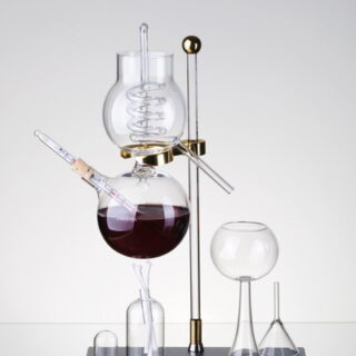
Custom made glass products
Read moreIn cooperation with a glass company that manufactures custom glass electrochemical cells for BVT, we offer a unique opportunity to manufacture custom glass products according to customer requirements.
This may include electrochemical flasks, cells, distillation columns and utility glass in dimensions and shapes that meet the customer’s requirements.
-
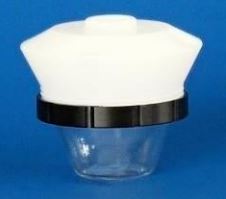
TC9 Electrochemical Glass Cell
Read moreBorosilicate glass cell serves for electrochemical measurements.
The analyzed solution can be thermostated by external thermostat MT1-1.
Cell openings are designed for stirrer ST9 or mini RDE and connector KA9.s with folder for electrochemical sensor AC9C, classical electrodes WCEc, ACEc and RCEc. The device enables the measurement with inserted samples.
-
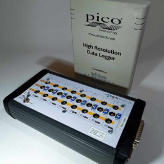
8/16-Channel Potentiostat for High Resolution Data Logger
Read moreThe device consists of a combination of an multi-channel potentiostat/converter (BVT Technologies) and an external USB Pico ADC high resolution data logger (Pico Technology).
The data logger can be supplied in two versions: ADC-20 (20 bits, 8 channels) or ADC-24 (24 bits, 16 channels). For detailed specifications, see the attachment at the end of the document. The device allows measurements from up to 8 or from up to 16 independent channels. The basic output signal is a voltage in the range of -2.5 to 2.5 V. All channels are programmable (the output can be concentration, temperature, pressure…).
After connecting the device to a PC with Pico Technology’s Picolog 6 measurement program installed, the voltage [V] can be processed using math channels and directly recorded in real time as temperature, current, resistance, frequency, % and pressure, see measurement example at the end of the document.
For temperature measurement, the device is compatible with resistance thermometers (Ni 1000, Ni 5000, Pt 1000. Power is provided via USB-B, the maximum electrical consumption of the device is 500 mA.
Device Usage
- Temperature measurement with different temperature sensor (resistance thermometers Ni 1000, ni 5000, Pt 1000)
- Voltage measurement
- Conductivity and resistance measurement
- Amperometry measurement
* For this product, we recommend our customers use the Training Service from BVT.
(https://bvt.cz/produkt/offer-of-long-term-automated-measurements-on-bvt-apparatus/)
-

ZIVE SP1 – potentiostat/galvanostat/ZRA
Read more- Potentiostat/galvanostat/ZRA at affordable price
- Control voltage range: ±10V
- Control current range:9 ranges, 10nA~1A (10nA with gain)
Application - Battery
- Super capacitor
- Fuel cell
- Corrosion
- Sensor
- Solar cell
- Other Echem experiments
Features
- economical high quality potentiostat/galvanostat/impedance analyzer
- compact size with full functions
- ±10V@1Amp control range
- wide current ranges(1A to 10nA) for various applications
- built-in FRA : enables EIS tests by using software
- 14 EIS techniques capability including multisine
- capable of multitude of applications
– corrosion, general electrochemistry, sensor, battery, fuel cell,
supercapacitor, solar cell, etc. - bipolar pulse capability
- voltage pulse or current pulse charge/discharge test(GSM,CDMA etc.),
sine wave function for ripple simulation withenergysoftwarepackage
& pulse plating available - high speed data sampling time
– 2usec or 3usec depending on data point number - iR compensation and measurement
- 3 measurement/control voltage ranges &
9 measurement/control current ranges - internal 542,000 data point storage & continuing experiment regardless
of PC failure. - multichannel configuration available
- free software upgrade
Experimental Techniques
Basic techniques
- Potentiostatic
- Galvanostatic
- Double step potentiostatic
- Double step galvanostatic
- OCP measurement
- Potential sweep
- Current sweep
- Cyclic voltammetry
- Fast potential sweep
- Potentiostatic Ru measurement
- Galvanostatic Ru measurement
Advanced Software Package(Included)
- EIS software package(EISe)
– Potentiostat EIS
– Galvanostatic EIS
– Pseudo galvanostatic EIS
– OCP* EIS
– Potentiodynamic PEIS
– Galvanodynamic GEIS
– Poteniodynamic HFR
– Galvanodynamic HFR
– Potentiostatic HFR monitor
– Galvanostatic HFR monitor
– Multisine potentiostatic EIS
– Multisine galvanostatic EIS
– Intermittent potentiostatic EIS
– Intermittent galvanostatic EIS
(*) The system measures open circuit potential before each frequency
change and applies AC sine wave on this potential. - Corrosion software package(CORe)
– Tafel(Tafel experiment)
– Rp(Polarization resistance)
– RpEc trend
– PDYN(Potentiodynamic)
– CYPOL(Cyclic polarization resistance)
– GDYN(GalvanoDynamic)
– Reactivation
– Galvanic corrosion
– Potentiostatic ECN
– Galvanostatic ECN
– ZRA mode ECN - Energy software package(BATe)
a) Battery test technique
– CC/CV testforcycle life test of lithium battery
– CC/CC tet forcyclelifetestofNiCd or NiMH battery
– Discharging test
– EVS(electrochemical voltage spectroscopy)
– Variable scan rate CV
– Potentiostatic IV curve
– Galvanostatic IV curve
– Steady state CV
– PITT(Potentiostatic intermittent titration technique) test
– GITT(Galvanostatic intermittent titration technique) test
– Pulse mode is available for GSM & CDMA profile.
Pulse shape profile can be measured by user’s demand.
b) Control mode
– Charge : CC, CC-CV, pulse, sine wave
– Discharge : CC, CP, CR, pulse, sine wave
c) Cut-off condition
– Time, voltage, current, power, auxV etc.
– Various battery charge/discharge test is available including
pulse discharge for GSM, CDMA application - Electrochemical analysis software package(EASe)
a) Step techniques
– CA(Chronoamperometry)
– CC(Chronocoulometry)
– CP(Chronopotentiometry)
b) Sweep techniques
– LSV(Linear sweep voltammetry)
– SDV(Sampled DC voltammetry)
– Fast CV
– Fast LSV
c) Pulsed techniques
– DPV(Differential pulse voltammetry)
– SWV(Square wave voltammetry)
– DPA(Diff.pulse amperometry)
– NPV(Normal pulse voltammetry)
– RNPV(Reverse normal pulse voltammetry)
– DNPV(Differential normal pulse voltammetry)