


Three Electrode Battery Test Cell – compression controlled (redox.me)
This cell is designed as high-quality alternative to Swagelok-type constructions for reproducible electrochemical measurements of battery and supercapacitor materials.
The cell consists of two main elements:
(i) the cell base with micrometre screw and compression spring, which allows precise control of pressure applied to the electrode sandwich; and
(ii) electrode cartridge where the anode, cathode and reference electrode are located.
The (default) electrode cartridge and plungers are designed for planar electrodes with diameter of 18 mm and total sandwich thickness of 2.5 mm. The diameter of separator shall be at least 2 mm larger than electrode diameter (max. 22 mm). The lock ring secures the separator in the electrode cartridge allowing easy and safe electrodes insertion, while ensuring accurate alignment. The upper and lower electrode plungers are available in various materials: 316L Stainless Steel (default), copper, aluminum, nickel etc. The pin-type reference electrode is installed from the side of the electrode cartridge. Thanks to sharp edged hole at the end of the pin the reference electrode (Li/Na/K etc.) can be easily punched from the metal foil and directly loaded into cell. The magnetic mount facilitates rapid assembly of the cartridge in the cell base. The force applied to the electrodes can reach up to 90N and is adjusted with the micrometer control knob. For 2-electrode measurements, the reference electrode feedthrough hole can be closed with the reference electrode punch.
The cell elements are constructed with materials that are inert to the sample (Stainless steel and PEEK). It well fits aqueous (FKM and EPDM O-Rings) and organic solvent (FFKM O-Rings) electrolyte requirements. Good electrical contact is ensured by gold plated pins. The construction is gas-tight and can be effortlessly assembled in the glove box, reducing possible human error to minimum.
Application note:
This cell can be used for all common battery measurements, such as galvanostatic cycling, cyclic voltammetry or electrochemical impedance spectroscopy. Both liquid and solid-state or gel-polymer electrolytes can be studied. Additionally, properties and performance of supercapacitor materials can be investigated. Various materials can be examined, including typical Li-ion electrodes (graphite, NMC, LTO etc.) and other chemistries – sodium, magnesium, potassium etc. It can also be applied to measure the ionic conductivity of separators and electrolytes. Owing to the micrometer control knob, the relationship between the initial pressure applied to the cell and the performance of solid-state electrolytes or metal plating process (anode-free systems) can be studied.
The above graph shows relation of pressure applied to electrode stack and distance travelled from the point of contact. The point of contact can be determined by checking OCV (see manual video) or by calculation. To calculate the point of contact, subtract electrode stack thickness from 4 mm. For example, for the 0.9 mm stack, the point of contact (i.e. reading on micrometer screw) will be 4 mm – 0.9 mm = 3.1 mm. Therefore, you should set micrometer screw to 3.1 mm and measure distance/pressure relation from this point.
Specification:
recommended electrode diameter: 18 mm (other options: 12 mm, 15 mm, 16 mm)
recommended minimum separator diameter: electrode diameter + 2 mm (max. 22 mm)
maximum electrode sandwich thickness: 2.5 mm
spring rate: 10.86 N/mm
maximum spring load: 90 N
operating temperature: -40°C – 80°C (default)
Intrastat data:
HS Code: 90309000
Country of Origin: Sweden
NET weight: 400g
Product includes:
1 x cell base
1 x compression control unit
1 x Three-Electrode Cartridge
1 x reference electrode punch
1 x upper plunger (Stainless Steel)
1 x lower plunger (Stainless Steel)
1 x separator locking ring
1 x gold plated piston
1 x compression spring
2 x gold plated pin contact
1 x set of O-rings
1 x set of 3 cable adapters 1mm to 4mm banana plug
1 x electrode plunger removal tool
Select configuration
Variant: water based / organic electrolyte
Related products
-

Basic electrochemical cell setup (redox.me)
Read moreThis is a stationary solution basic electrochemical cell for measurements of electrodes in a form of:
a) rod/disc (6 mm dia.),
b) thin film deposited on a flat substrate (using a wire clip) and
c) membrane (using a wire clip).
The working, counter, and reference electrodes are mounted in a top casing either in 2-, or 3-electrode setup. The cell elements are constructed with materials that are inert to the sample (glass and PEEK). It well fits aqueous (FKM/EPDM O-Rings) and organic solvent (FFKM O-Rings) electrolyte requirements. The construction is gas-tight and can be used when the removal and exclusion of contaminants such as oxygen and water is required by bubbling of an inert gas through the electrolyte. The cell chamber is available in several material variants here (glass, PTFE, PEEK)
Application note:
The reference electrode tip should be placed at the level of working electrode center. This will ensure a low potential drop throughout the electrolyte solution for low-current experiment. Various auxiliary electrodes are suitable for this cell including metal wire and metal foil electrodes as well as graphite rod. The bubbling of gas through the solution must be stopped prior to experiment.Specification:
maximum electrolyte volume: 50 mL
electrode plug diameter: 6 mm
number of electrode slots: 3Intrastat data:
HS Code: 90309000
Country of Origin: Sweden
NET weight: 200 gSetup includes:
Item Qty B-A-BEC-50 B-O-BEC-50 BEC 50 mL – Basic Electrochemical Cell 1 C-A-BEC-50 C-O-BEC-50 Metal wire auxiliary electrode – 50HX15 0.6/250 mm, platinum (99,9%), 1 mm dia. gold plated pin 1 E-A-50HX15_Pt-1mm E-O-50HX15_Pt-1mm Silver / Silver Chloride Reference Electrode – Ag/AgCl 70 mm 1 E-Ag/AgCl_70 Non-aqueous Silver / Silver Ion Reference Electrode – Ag/Ag+ 70 mm 1 E-Ag/Ag+_70 Working disk electrode – 2 mm dia., PEEK BODY 6 mm dia. – 70 mm, glassy carbon 1 E-A-DISK_GC-70 E-O-DISK_GC-70 10 pcs of Tantalum wire clip with septum plug 0.6 mm dia., 60 mm long 1 E-A-Ta_CLIP-0.6/60-10p E-O-Ta_CLIP-0.6/60-10p -
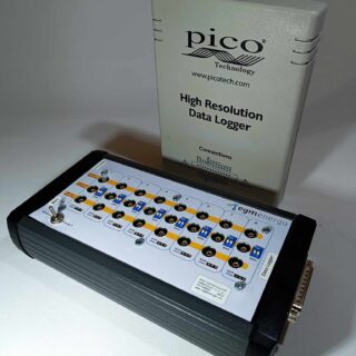
8/16-Channel Potentiostat for High Resolution Data Logger
Read moreThe device consists of a combination of an multi-channel potentiostat/converter (BVT Technologies) and an external USB Pico ADC high resolution data logger (Pico Technology).
The data logger can be supplied in two versions: ADC-20 (20 bits, 8 channels) or ADC-24 (24 bits, 16 channels). For detailed specifications, see the attachment at the end of the document. The device allows measurements from up to 8 or from up to 16 independent channels. The basic output signal is a voltage in the range of -2.5 to 2.5 V. All channels are programmable (the output can be concentration, temperature, pressure…).
After connecting the device to a PC with Pico Technology’s Picolog 6 measurement program installed, the voltage [V] can be processed using math channels and directly recorded in real time as temperature, current, resistance, frequency, % and pressure, see measurement example at the end of the document.
For temperature measurement, the device is compatible with resistance thermometers (Ni 1000, Ni 5000, Pt 1000. Power is provided via USB-B, the maximum electrical consumption of the device is 500 mA.
Device Usage
- Temperature measurement with different temperature sensor (resistance thermometers Ni 1000, ni 5000, Pt 1000)
- Voltage measurement
- Conductivity and resistance measurement
- Amperometry measurement
* For this product, we recommend our customers use the Training Service from BVT.
(https://bvt.cz/produkt/offer-of-long-term-automated-measurements-on-bvt-apparatus/)
-

Raman Electrochemical Flow Cell, active area: 3.5 cm2, volume: 4.5 mL (redox.me)
Read moreThis cell combines two classical analytical techniques such as electrochemistry and Raman spectroscopy, to obtain in-situ chemical information about the reactions taking place during an electrochemical experiment. It consists mainly of three elements: (i) sample holder with Tantalum (formerly Copper) foil serving as an electric contact to working electrode surface, (ii) chamber in which reference and counter electrodes are installed together with electrolyte inlet and outlet and (iii) lid which seals the cell and holds the Sapphire window. The sample consisting of a thin film of electrochemically active material deposited on a rigid or flexible substrate (working electrode) is loaded from the bottom via magnetic or screw mount. The counter or/and reference electrodes are mounted in a top casing (either 2-, or 3-electrode setup. The oval counter electrode made of e.g. Platinum wire assures uniform distribution of the field lines along the path to working electrode. During an experiment Raman laser is focused onto the surface of a thin film working electrode through a transparent Sapphire window and thin layer of electrolyte (total optical path of 3.25 mm). The electrolyte thickness of 2.25 mm ensures free diffusion of ions (e.g. protons) and its counter ions.
The electrode adapter for installing 6 mm dia. electrodes inside Raman ECFC is available here. It enables using disk electrode, plug with clip or any other rod-shape electrode (e.g. graphite rod) or current collector (e.g. metal mesh, graphite coated metal mesh, metal foil, graphite coated metal foil, metal foam, carbon woven and non-woven fabrics, carbon paper, etc.) as working electrode instead of a flat electrode in default Raman ECFC configuration.
The screw mount variant of Raman ECFC can be converted into GDE Raman ECFC by using Gas Compartment. This conversion allows installation of Gas Diffusion Electrodes as working electrode.
The cell elements are constructed with materials that are inert to the sample (PEEK, Fluorocarbons). It well fits aqueous (FKM O-Rings) and organic solvent (FFKM O-Rings) electrolyte requirements. The construction is gas-tight and can be used when the removal and exclusion of contaminants such as oxygen and water is required by bubbling of an inert gas through the electrolyte (in an external reservoir).
Application note:
This cell can be used to track kinetic phenomena such as the near-surface proton concentration changes during oxidation and reduction reaction at working electrode. It can be also used to identify materials such as carbon, metal oxides, polymers and electrolytes, and to determine their structure and distribution. Various metals are suitable for this cell as auxiliary electrode including Platinum, Gold and Silver.Specification:
nominal exposure area: 3.5 cm2
electrolyte volume: 4.5 mL
optical path (including Sapphire window): 3.25 mm
electrode plug diameter: 6 mmIntrastat data:
HS Code: 90275000
Country of Origin: Sweden
NET weight: 200 gProduct includes:
1 x chamber
1 x Reference electrode (Ag/AgCl, or Ag/Ag+), 30mm
1 x Metal wire auxiliary electrode – ST 0.6/150 mm, Platinum
1 x Sapphire window – 0054PSPCM
1 x lid
1 x WE Tantalum contact
1 x sample holder
1 x plug – 0005CPEMA -

Bottom mount front contact electrochemical cell setup (redox.me)
Read moreThis is a static voltammetry cell with variants for different sample dimensions. The sample is loaded from the bottom via magnetic or screw mount, while counter or/and reference electrodes are mounted in the lid as either 2-, or 3-electrode configuration. The cell is constructed with materials that are inert to the sample environment (glass and PEEK), and it can be used with FKM/EPDM O-rings or FFKM O-rings for aqueous or organic electrolyte requirements, respectively. The construction is gas-tight and inert gas can be bubbled through the electrolyte to remove and exclude contaminants such as air or water.
Application note:
The reference electrode tip should be placed close to the sample surface to ensure a negligible potential drop throughout the electrolyte solution during low-current experiments. In the magnetic variant of the cell, the strength with which the magnets hold the sample is adjusted by adding or removing the washers under the magnets. Thanks to this procedure, the distance between the magnets changes, with it, the force of their attraction. Various auxiliary electrodes are suitable for this cell, including metal wire and metal plate electrodes as well as carbon-based electrodes (graphite or Glassy Carbon). If a purge gas is used, stop the flow during experiments for better results.Specification:
nominal exposure area: 0.07 cm2 for 5x5mm2, 0.2 cm2 for 7x7mm2, 0.5 cm2 for 10x10mm2, and 1.33 cm2 for 15x15mm2
minimum electrolyte volume: 2.5 mL
maximum electrolyte volume: 15 mL
electrode plug diameter: 6 mm
substrate size: 5x5mm2, 7x7mm2, 10x10mm2, and 15x15mm2, other sizes available on request
minimum substrate thickness: 0.4 mm**lower thicknesses are also feasible when using a pad below the sample
Intrastat data:
HS Code: 90309000
Country of Origin: Sweden
NET weight: 200 gSetup includes:
1 x BM FC EC 15mL – Bottom Mount Front Contact Electrochemical Cell, 15mL (or BMM FC EC 15mL – Bottom Magnetic Mount Front Contact Electrochemical Cell, 15mL)
1 x lid
1 x glass chamber
1 x bottom casing
1 x sample mount
1 x tantalum contact
1 x plug
1 x set of Nylon screws (screw variant only)
1 x Reference electrode (Ag/AgCl, or Ag/Ag+), 70mm, 4 mm female banana socket
1 x Metal Wire Auxiliary Electrode – 50HX15 0.6/250 mm, platinum 99.9%, 4 mm female banana socket