


Raman Electrochemical Flow Cell, active area: 3.5 cm2, volume: 4.5 mL (redox.me)
This cell combines two classical analytical techniques such as electrochemistry and Raman spectroscopy, to obtain in-situ chemical information about the reactions taking place during an electrochemical experiment. It consists mainly of three elements: (i) sample holder with Tantalum (formerly Copper) foil serving as an electric contact to working electrode surface, (ii) chamber in which reference and counter electrodes are installed together with electrolyte inlet and outlet and (iii) lid which seals the cell and holds the Sapphire window. The sample consisting of a thin film of electrochemically active material deposited on a rigid or flexible substrate (working electrode) is loaded from the bottom via magnetic or screw mount. The counter or/and reference electrodes are mounted in a top casing (either 2-, or 3-electrode setup. The oval counter electrode made of e.g. Platinum wire assures uniform distribution of the field lines along the path to working electrode. During an experiment Raman laser is focused onto the surface of a thin film working electrode through a transparent Sapphire window and thin layer of electrolyte (total optical path of 3.25 mm). The electrolyte thickness of 2.25 mm ensures free diffusion of ions (e.g. protons) and its counter ions.
The electrode adapter for installing 6 mm dia. electrodes inside Raman ECFC is available here. It enables using disk electrode, plug with clip or any other rod-shape electrode (e.g. graphite rod) or current collector (e.g. metal mesh, graphite coated metal mesh, metal foil, graphite coated metal foil, metal foam, carbon woven and non-woven fabrics, carbon paper, etc.) as working electrode instead of a flat electrode in default Raman ECFC configuration.
The screw mount variant of Raman ECFC can be converted into GDE Raman ECFC by using Gas Compartment. This conversion allows installation of Gas Diffusion Electrodes as working electrode.
The cell elements are constructed with materials that are inert to the sample (PEEK, Fluorocarbons). It well fits aqueous (FKM O-Rings) and organic solvent (FFKM O-Rings) electrolyte requirements. The construction is gas-tight and can be used when the removal and exclusion of contaminants such as oxygen and water is required by bubbling of an inert gas through the electrolyte (in an external reservoir).
Application note:
This cell can be used to track kinetic phenomena such as the near-surface proton concentration changes during oxidation and reduction reaction at working electrode. It can be also used to identify materials such as carbon, metal oxides, polymers and electrolytes, and to determine their structure and distribution. Various metals are suitable for this cell as auxiliary electrode including Platinum, Gold and Silver.
Specification:
nominal exposure area: 3.5 cm2
electrolyte volume: 4.5 mL
optical path (including Sapphire window): 3.25 mm
electrode plug diameter: 6 mm
Intrastat data:
HS Code: 90275000
Country of Origin: Sweden
NET weight: 200 g
Product includes:
1 x chamber
1 x Reference electrode (Ag/AgCl, or Ag/Ag+), 30mm
1 x Metal wire auxiliary electrode – ST 0.6/150 mm, Platinum
1 x Sapphire window – 0054PSPCM
1 x lid
1 x WE Tantalum contact
1 x sample holder
1 x plug – 0005CPEMA
Select configuration
Electrolyte type: water-based / organic electrolyte
Mount type: magnetic / screw
Operating video manual
Related products
-

Front contact photo-electrochemical H-Cell setup (redox.me)
Read moreThis is a horizontally mounted, double compartment photo-electrochemical H-Cell used to simultaneously or individually investigate thin film photo-anode and photo-cathode. The cell elements are made of PEEK and Fluoropolymers. It well fits aqueous (FKM O-Rings) and organic solvent (FFKM O-Rings) electrolyte requirements. The construction is gas-tight having two separate chambers, each equipped with gas inlet and outlet. This allows bubbling the solution and evacuating gases. Chambers are separated with an ion-exchange membrane (e.g., DuPont’s Nafion® membrane), so the electrochemical products appearing at photo-anode and (photo-)cathode do not affect the opposite electrode.
Application note:
This cell allows several approaches to perform measurements in 2- or 3-electrode setups. It is designed to investigate performance of a thin film photo-anode or photo-cathode (e.g. nanocrystalline material or conducting polymer) deposited on a rigid or flexible transparent substrate (typically fused quartz glass). The counter electrode is mounted in the second chamber either in a top casing or attached on the side of the cell as a thin film deposited on rigid or flexible substrate. The reference electrode is mounted in a top casing of the same chamber as the studied photo-electrode. Various auxiliary electrodes are suitable for this cell including metal wire, gauze and foil electrodes as well as non-metal electrodes and thin films. Typical applications include: basic photochemistry (photo-catalysis), photolytic water splitting, photoinduced charge separation and photo-corrosion.Specification:
minimum electrolyte volume: 2×10 mL
maximum electrolyte volume: 2×15 mL
electrode plug diameter: 6 mm
maximum substrate thickness: 3 mmIntrastat data:
HS Code: 90309000
Country of Origin: Sweden
NET weight: 600gSetup includes:
1 x Front Contact Photo-Electrochemical H-Cell
2 x lid – 0001CPEMA
2 x chamber
2 x sample mount
2 x Tantalum contacts
1 x micro tripod
4 x plug
1 x set of O-Rings (18 pcs)
1 x Metal Wire Auxiliary Electrode – 50HX15 0.6/250 mm (Platinum)
2 x Reference electrode (Ag/AgCl, or Ag/Ag+), 30 mm -
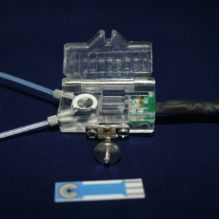
FC2.TL.* PMMA Flow Cell
Read moreThe flow cell enables the use of Screen printed sensors in a flow through arrangement.
The flow cell is suitable for sensors of type AC1, AC2, CC1, CC2 and CC3.
The Screen printed sensor is inserted into the slit of cell and tightened by closing of the door. The cell ensures the wall-jet flow around the working electrode and it is optimised so that no air bubbles cumulate in the cell. The cell contains also the contact and output cable.
With the sensors enclosed in a flow cell, it is possible to measure semi-automatically or automatically using a pump or liquid switch for sample supply. Under such conditions, maximum measurement reproducibility is ensured.
-
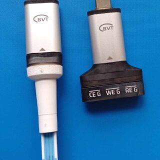
USB Potentiostat Galvanoplot
Read moreUSB Potentiostat Galvanoplot is a super small, low-cost and affordable device suitable for dedicated volume applications, which is optimized for screen-printed sensor and biosensor applications. It can be used in many other research areas and with other electrochemical sensors, for corrosion measurement, battery and super-capacitors or fuel cells.
It is capable of performing all common Amperometric and Voltammetric electrochemistry protocols (CA, LSV, CV, DPV, NPV, SVW, GAL) and can be used with three electrode (WE/RE/CE) and two electrode (WE/RE-CE) setups. Plug the device directly into an Android mobile device through OTG port for a true on-site analysis experience. It is possible to choose from two types of interfaces allowing direct insertion of the BVT SPE sensors or the use of 3 classical electrodes with 2 mm banana plugs (WE, RE, CE).
- Dimensions: 39x17x8 mm
- Weight: 5 g without sensor interface
- Voltage scan range: +-3V @1mV resolution
- Max current: 2000 nA (*at the request of the customer, it is possible to change the range, but this will change the resolution, noise and other parameters)
- Current resolution: 300pA@1KSPS/ 100pA@100SPS/ 30pA/10 SPS resolution
- Noise around: 50nA@1KSPS/ 7nA@100SPS/ 400pA/10 SPS
- Protocols: CA, LSV, CV, DPV, NPV, SVW, GAL
- Cell type: WE/RE/CE and WE/RE-CE
Connectivity: USB-C (Plug the device directly into an Android mobile device through OTG port for a true on-site analysis experience)
- Operating system compatibility: Windows 8, 10+
- Advanced analysis – filtering and auto peaks
Device Usage
- Electrochemical measurements
- Measurements with biosensors and electrochemical sensors
- Measurement of biochemical activity of a sample
- Corrosion measurement
-

Spectro-electrochemical flow cell setup (redox.me)
Read moreThis is a horizontally mounted, multi-purpose spectroelectrochemical cell designed to be used with standard UV-Vis or IR spectrometers. It enables obtaining electrochemical and spectroscopic information from liquid sample or thin films in systems where variations in applied potential induce changes in observed spectra. It consists of a polyether ether ketone (PEEK) flow chamber equipped with a magnetic or screw mount sample holder, screw mount quartz window holder and two different mini tripods. It well fits aqueous (FKM O-Rings) and organic solvent (FFKM O-Rings) electrolyte requirements.
The cell is meant to be used with a standard reference electrode having 6 mm in diameter and a counter electrode either in the form of a rod or helix with 6 mm in diameter and 15 mm active length.
Application note:
The spectroelectrochemical cell is used to study the relation between absorbance/transmittance and electrochemical potential. It enables real-time monitoring of optical change in electrochromic materials. It also enables in-situ spectral acquisition for detection, identification and characterization of short-lived electrochemically-generated species/intermediates, resulting in a detailed investigation of the mechanistic pathways of redox processes.Specification:
nominal exposure area: 1 cm2 (other values on request)
optical path length (electrolyte thickness): 12 mm
flow chamber volume: 1.75 mL
maximum substrate thickness: 4 mm
electrode plug diameter: 6 mm
minimum substrate size: 17 mm x 25 mm
recommended substrate size: 25 mm x 25 mmIntrastat data:
HS Code: 90275000
Country of Origin: Sweden
NET weight: 300 gSetup includes:
1 x Magnetic Mount Spectro-Electrochemical Flow Cell – MM spectro-EFC 1.75 mL (or Spectro-Electrochemical Flow Cell – spectro-EFC 1.75 mL)
1 x Metal Wire Auxiliary Electrode – 35HX15 0.6/235 mm (Platinum)
1 x Reference electrode (Ag/AgCl, or Ag/Ag+)