
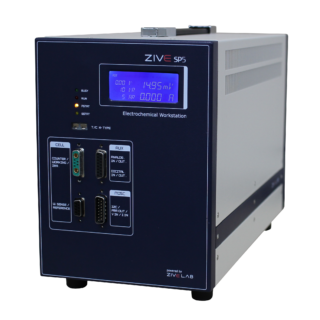
ZIVE SP2 – high quality potentiostat/galvanostat/impedance analyzer
- Versatile high quality potentiostat/galvanostat/impedance analyzer
- Control voltage range: ±10V, ±1V, ±100mV
- Control current range: 200pA ~ 2A (200pA with gain, 11 ranges)
Application
Features
Experimental Techniques Basic techniques
Advanced software techniques(Included)
Options
|
The specifications are subject to change without notice. |
Related products
-

ZIVE MP1-4CH housing – high quality multichannel potentiostat/galvanostat/impedance analyzer
Read more- High quality multichannel potentiostat/galvanostat/impedance analyzer
- Voltage range : ±10V
- Current range : 100nA~1A (10nA with gain)
- Channel expandable up to 16 channels per PC
Application
- Corrosion
- Material testing
- Sensor
- Bio-Electrochemistry
- Battery / Supercapacitor
- Fuel cell
- Solar cell
- Other Echem experiments
Features
- high quality multichannel potentiostat/galvanostat/impedance analyzer
- voltage range : ±10V
- current range : 9 ranges
– 100nA to 1A (10nA with gain) - capable of multitude of applications
– corrosion, general electrochemistry, sensor, battery, fuel cell,
supercapacitor, solar cell, etc. - plug & play type fully independent channel
- channel expandable up to 16 channels per PC
- frequency range : 10uHz ~ 1Mhz
- 14 EIS techniques capability including multisine
- voltage pulse or current pulse charge/discharge test(GSM,CDMA etc.),
sine wave function for ripple simulation in energy software package
& pulse plating available - high speed data sampling time
– 2usec or 3usec depending on data point numbers - fast sweep mode(5000V/sec with 10mV data sampling)
- iR compensation and measurement
- 3 measurement/control voltage ranges &
9 measurement/control current ranges - internal 542,000 data point storage & continuing experiment regardless
of PC failure. - can be interfaced to a separate booster for high current applications
- one auxiliary voltage measurement is available
- inclues basic software, Energy/Impedance/Battery/Echem analysis software packages
- free software upgrade
Experimental Techniques
Basic techniques
- Potentiostatic
- Galvanostatic
- Double step potentiostatic
- Double step galvanostatic
- OCP measurement
- Potential sweep
- Current sweep
- Cyclic voltammetry
- Fast potential sweep
- Potentiostatic Ru measurement
- Galvanostatic Ru measurement
Advanced Software Package(Included)
- EIS software package(EISe)
– Potentiostat EIS
– Galvanostatic EIS
– Pseudo galvanostatic EIS
– OCP* EIS
– Potentiodynamic PEIS
– Galvanodynamic GEIS
– Poteniodynamic HFR
– Galvanodynamic HFR
– Potentiostatic HFR monitor
– Galvanostatic HFR monitor
– Multisine potentiostatic EIS
– Multisine galvanostatic EIS
– Intermittent potentiostatic EIS
– Intermittent galvanostatic EIS
(*) The system measures open circuit potential before each frequency
change and applies AC sine wave on this potential. - Corrosion software package(CORe)
– Tafel(Tafel experiment)
– Rp(Polarization resistance)
– RpEc trend
– PDYN(Potentiodynamic)
– CYPOL(Cyclic polarization resistance)
– GDYN(GalvanoDynamic)
– Reactivation
– Galvanic corrosion
– Potentiostatic ECN
– Galvanostatic ECN
– ZRA mode ECN - Energy software package(BATe)
a) Battery test technique
– CC/CV testforcycle life test of lithium battery
– CC/CC tet forcyclelifetestofNiCd or NiMH battery
– Discharging test
– EVS(electrochemical voltage spectroscopy)
– Variable scan rate CV
– Potentiostatic IV curve
– Galvanostatic IV curve
– Steady state CV
– PITT(Potentiostatic intermittent titration technique) test
– GITT(Galvanostatic intermittent titration technique) test
– Pulse mode is available for GSM & CDMA profile.
Pulse shape profile can be measured by user’s demand.
b) Control mode
– Charge : CC, CC-CV, pulse, sine wave
– Discharge : CC, CP, CR, pulse, sine wave
c) Cut-off condition
– Time, voltage, current, power, auxV etc.
– Various battery charge/discharge test is available including
pulse discharge for GSM, CDMA application - Electrochemical analysis software package(EASe)
a) Step techniques
– CA(Chronoamperometry)
– CC(Chronocoulometry)
– CP(Chronopotentiometry)
b) Sweep techniques
– LSV(Linear sweep voltammetry)
– SDV(Sampled DC voltammetry)
– Fast CV
– Fast LSV
c) Pulsed techniques
– DPV(Differential pulse voltammetry)
– SWV(Square wave voltammetry)
– DPA(Diff.pulse amperometry)
– NPV(Normal pulse voltammetry)
– RNPV(Reverse normal pulse voltammetry)
– DNPV(Differential normal pulse voltammetry)
Options
- Power booster
-

Silver / Silver Chloride Refillable Reference Electrode – 6 mm dia. (redox.me)
Read moreIt is a compact refillable Ag/AgCl reference electrode equipped with ceramic frit molten into the glass body. This electrode outperforms competing products in terms of mechanical stability, voltage stability and lifetime. In general, the reference electrode is composed of a system of phases, which retain an essentially constant composition, and therefore provides a stable potential by which the working electrode potential can be monitored. The phases present in reference electrodes undergo reversible redox processes at a very high rate, enabling them to rapidly adjust to changes in the solution’s ionic activity, but leaving them sensitive to the passage of large current densities.
Application note
This electrode is commonly used with aqueous acidic electrolytes, but due to the low resistance of the frit it can be used with standard non-aqueous electrolytes, as well. The reference electrode should be stored with the rubber plug applied on the tip. Please see the full instruction here. Keeping in the solution may shorten its lifetime (the electrode operates well as long as there is at least ¼ of the solution in the electrode tube). Before use rinse it with deionized water. If air bubbles are present around the porous frit, flick the tip several times to remove them. For cleaning use detergent (dish washing detergent with water), alcohols or acetone and rinse it with deionized water at the end. To re-fill the electrode please follow this article.Specification
effective length: 30 mm or 70 mm
tube diameter: 6 mm
filling solution: 3M KCl
potential stability: <5 mV
frit resistance: 2-10 kohm at RT
operating temperature: 0-100 deg C
potential vs SHE at 25 °C: 0.207 VIntrastat data
HS Code: 90278930
Country of Origin: Sweden
NET weight: 100gProduct includes
1 Ag/AgCl refillable reference electrode
1 O-Ring
1 glass tube for storing purposes -

Platinum Coated Titanium Mesh Electrode with Holder – set of 10 pcs (redox.me)
Read moreThe metal counter (auxiliary) electrode is provided in electrochemical cell as a current sink to shunt excess current away from the reference electrode. Platinum Coated Titanium Mesh Electrode is a cheap alternative to pure Platinum Electrodes like Platinum Gauze Electrode or Metal Wire Auxiliary Electrode. Platinum coating makes this counter electrode inert under the reaction conditions and provides catalytic properties. The electrode is installed in the Basic Sample Holder (1 pcs included in the set), which allows full immersion of the electrode in the electrolyte (wet Tantalum contact). It well fits aqueous and organic solvent electrolyte requirements. Electrode size is customizable.
Application note
The Platinum Coated Titanium Mesh Electrode is fully immersed in the ion-conducting solution as a counter electrode. An electric current is passed between the working electrode and the Platinum Coated Titanium Mesh Electrode for a certain amount of time. After the process, the electrode should be washed several times with ethanol and dried under the nitrogen flow. Store the electrode in a dedicated compartment to avoid scratching. Discoloration may indicate the degradation (dissolution) of the Platinum layer and oxidation of Titanium mesh.
This electrode is used mainly in systems where there is a high risk of its contamination by organic or inorganic deposit during the electrochemical reaction. It is also a cheap replacement for pure Platinum electrode in electrodeposition processes.Specification
Titanium grade: GR1
working current: <5000 A/m2
Platinum content: >15 g/m2
Platinum coating thickness: 760 – 1500 nm
mesh hole size: 3 mm x 2 mm
mesh thickness: 0.5 mm
electrode size: 25x25mm2, 50x50mm2, 100x100mm2, custom
pH range: 1-12Intrastat data
HS Code: 71151000
Country of Origin: Sweden
NET weight: 100 gProduct includes
10 x Platinum Coated Titanium Mesh Electrode of selected size
1 x Basic Sample Holder (if selected) -
ZIVE SP5 – high quality potentiostat/galvanostat/impedance analyzer
Read more- Versatile high quality potentiostat/galvanostat/impedance analyzer
- Control voltage range : ±10V, ±1V, ±100mV
- Control current range : 50pA ~ 5A (500pA with gain, 11 ranges)
Application
- Battery / Super capacitor
- Fuel cell
- Corrosion
- Sensor
- Solar cell
- Other Echem experiments
Features
- high quality potentiostat/galvanostat/impedance analyzer
- ±10V@5Amp control range
- current range (11 ranges)
– 5nA to 5A
– 500pA with gain - frequency range : 10uHz ~ 1MHz
- built-in FRA : enables EIS tests
- 14 EIS techniques capability(option) including multisine
- capable of multitude of applications
– corrosion, general electrochemistry, sensor, battery, fuel cell,
supercapacitor, solar cell, etc. - bipolar pulse capability
- voltage pulse or current pulse charge/discharge test(GSM,CDMA etc.),
sine wave function for ripple simulation in battery test package
& pulse plating available - high speed data sampling time
– 2usec or 3usec depending on data point numbers - fast sweep mode(5000V/sec with 10mV data sampling)
- iR compensation & measurement
- 3 measurement/control voltage ranges &
11 measurement/control current ranges - internal 542,000 data point storage & continuing experiment regardless
of PC failure. - LCD diaplay
- multichannel configuration available by connecting multiple SP5 or other ZIVE products
- external booster (ZIVE ZB series) available
- inclues basic software, Energy/Impedance/Battery/Echem analysis software packages
- can use EIS data analysis software, ZMANTM and DC data analysis software
IVMANTMwithough purchasing license code - free software upgrade
Experimental Techniques
Basic techniques
- Potentiostatic
- Galvanostatic
- Double step potentiostatic
- Double step galvanostatic
- OCP measurement
- Potential sweep
- Current sweep
- Cyclic voltammetry
- Fast potential sweep
- Potentiostatic Ru measurement
- Galvanostatic Ru measurement
Advanced software techniques(included)
- EIS software package(EIS)
– Potentiostat EIS
– Galvanostatic EIS
– Pseudo galvanostatic EIS
– OCP* EIS
– Potentiodynamic PEIS
– Galvanodynamic GEIS
– Poteniodynamic HFR
– Galvanodynamic HFR
– Galvanostatic HFR monitor
– Potentiostatic HFR monitor
– Multisine potentiostatic EIS
– Multisine galvanostatic EIS
– Intermittent potentiostatic EIS
– Intermittent galvanostatic EIS
(*) The system measures open circuit potential before each frequency
change and applies AC sine wave on this potential.
- Corrosion software package(COR)
– Tafel(Tafel experiment)
– Rp(Polarization resistance)
– RpEc trend
– PDYN(Potentiodynamic)
– CYPOL(Cyclic polarization resistance)
– GDYN(GalvanoDynamic)
– Reactivation
– Galvanic corrosion
– Potentiostatic ECN
– Galvanostatic ECN
– ZRA mode ECN
- Energy software package(BAT)
a) Battery test technique
– CC/CV test for cycle life test of lithium battery
– CC/CC tet for cycle life test of NiCd or NiMH battery
– Discharging test
– EVS(electrochemical voltage spectroscopy)
– Variable scan rate CV
– Potentiostatic IV curve
– Galvanostatic IV curve
– Steady state CV
– PITT(Potentiostatic intermittent titration technique) test
– GITT(Galvanostatic intermittent titration technique) test
– Pulse mode is available for GSM & CDMA profile.
Pulse shape profile can be measured by user’s demand.
b) Control mode
– Charge : CC, CC-CV, pulse, sine wave
– Discharge : CC, CP, CR, pulse, sine wave
c) Cut-off condition
– Time, voltage, current, power, auxV etc.
– Various battery charge/discharge test is available including
pulse discharge for GSM, CDMA application
- Electrochemical analysis software package(EAS)
a) Step techniques
– CA(Chronoamperometry)
– CC(Chronocoulometry)
– CP(Chronopotentiometry)
b) Sweep techniques
– LSV(Linear sweep voltammetry)
– SDV(Sampled DC voltammetry)
– Fast CV
– Fast LSV
c) Pulsed techniques
– DPV(Differential pulse voltammetry)
– SWV(Square wave voltammetry)
– DPA(Diff.pulse amperometry)
– NPV(Normal pulse voltammetry)
– RNPV(Reverse normal pulse voltammetry)
– DNPV(Differential normal pulse voltammetry)
Options
- Power booster