


Basic electrochemical H-cell setup (redox.me)
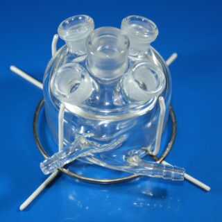
This is a stationary solution double compartment electrochemical H-Cell for measurements of electrodes in a form of:
a) rod/disc (6 mm dia.),
b) thin film deposited on a flat substrate (using a wire clip) and
c) membrane (using a wire clip).
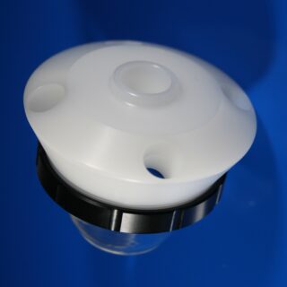
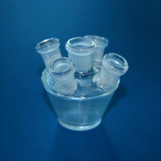
The working, counter and reference electrodes are mounted in a top casing either in 2-, or 3-electrode setup. The counter electrode is placed in a compartment separated from the other electrodes by ion-exchange membrane (19 mm to 25 mm dia.), so the electrochemical products appearing at working and counter electrode do not affect the opposite electrode. The counter electrode compartment is equipped with a separate inlet and outlet for easy filling with an electrolyte and evacuation of gaseous products. It can accommodate standard Metal Wire Auxiliary Electrode as well as square shape electrodes with sizes up to 25 mm x 25 mm. The cell elements are constructed with materials that are inert to the sample (glass and PEEK). It well fits aqueous (FKM/EPDM O-Rings) and organic solvent (FFKM O-Rings) electrolyte requirements. The construction is gas-tight and can be used when the removal and exclusion of contaminants such as oxygen and water is required by bubbling of an inert gas through the electrolyte. After removal of the counter electrode glass compartment, the cell gets the functionality of a Basic Electrochemical Cell – BEC 50 mL.
The cell chamber is available in several material variants here.
Application note:
The reference electrode tip and working disk electrode tip should be placed in the middle of the membrane. This will ensure a low potential drop throughout the electrolyte solution for low-current experiment. Various auxiliary electrodes are suitable for this cell including metal wire and metal foil/mesh/foam electrodes as well as graphite rod. The bubbling of gas through the solution must be stopped prior to experiment.
Specification:
minimum electrolyte volume in WE compartment: 22 mL
minimum electrolyte volume in CE compartment: 6 mL
maximum electrolyte volume: 40 mL
minimum membrane diameter: 19 mm
maximum membrane diameter: 25 mm
maximum membrane thickness: 0.5 mm
electrode plug diameter: 6 mm
number of electrode slots: 3
Intrastat data:
HS Code: 90309000
Country of Origin: Sweden
NET weight: 200 g
Setup includes:
1 x BE H-Cell 50 mL – Basic Electrochemical H-Cell 50 mL
1 x Metal Wire Auxiliary Electrode – 50HX15 0.6/250 mm (Platinum)
1 x Reference electrode (Ag/AgCl, or Ag/Ag+)
1 x Glassy Carbon disk electrode – 2 mm dia.
1 x Plug with silicone rubber septum and set of Tantalum wire clips (set of 10)
Select configuration
Variant: water based / organic electrolyte
Related products
-
TC5 Electrochemical Glass Cell
Read moreBorosilicate glass cell serves for electrochemical measurements. The cell is jacketed.
The analyzed solution can be thermostated by external thermostat.
Cell openings are designed for electrochemical sensors connector KA1.C, classical electrodes WCEc, ACEc, RCEc and stirrer ST1, ST3 separately.
-
TC6 Electrochemical Glass Cell
Read moreBorosilicate glass cell serves for electrochemical measurements.
The analyzed solution can be thermostated by minithermostat MT1-1.
Cell openings are designed for electrochemical sensors connector KA1.C, classical electrodes WCEc, ACEc, RCEc and stirrer ST1, ST3 separately.
The device enables the measurement with inserted samples.
-
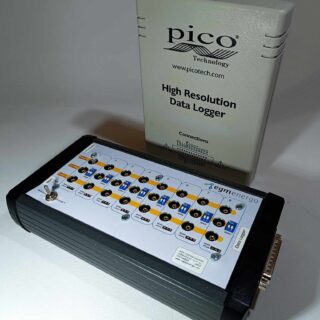
8/16-Channel Potentiostat for High Resolution Data Logger
Read moreThe device consists of a combination of an multi-channel potentiostat/converter (BVT Technologies) and an external USB Pico ADC high resolution data logger (Pico Technology).
The data logger can be supplied in two versions: ADC-20 (20 bits, 8 channels) or ADC-24 (24 bits, 16 channels). For detailed specifications, see the attachment at the end of the document. The device allows measurements from up to 8 or from up to 16 independent channels. The basic output signal is a voltage in the range of -2.5 to 2.5 V. All channels are programmable (the output can be concentration, temperature, pressure…).
After connecting the device to a PC with Pico Technology’s Picolog 6 measurement program installed, the voltage [V] can be processed using math channels and directly recorded in real time as temperature, current, resistance, frequency, % and pressure, see measurement example at the end of the document.
For temperature measurement, the device is compatible with resistance thermometers (Ni 1000, Ni 5000, Pt 1000. Power is provided via USB-B, the maximum electrical consumption of the device is 500 mA.
Device Usage
- Temperature measurement with different temperature sensor (resistance thermometers Ni 1000, ni 5000, Pt 1000)
- Voltage measurement
- Conductivity and resistance measurement
- Amperometry measurement
* For this product, we recommend our customers use the Training Service from BVT.
(https://bvt.cz/produkt/offer-of-long-term-automated-measurements-on-bvt-apparatus/)
-
TC4 Electrochemical Glass Cell
Read moreSimple borosilicate glass cell serves for electrochemical measurements.
The temperature of the analyzed solution can be controlled when placing the cell in MT1-1 minithermostat.
Cell openings are designed for electrochemical sensors connector KA1.C, classical electrodes WCEc, ACEc, RCEc and stirrer ST1, ST3 separately.