

STK-C Customer Starting kit
Starting Kit STK.S-C
The customer starter kit is a set of twenty different electrochemical sensors to find the best one that suits your application.
The starter set contains at least 5 pcs of sensors type AC1.W*.R* from the given type of sensors with a working electrode diameter (Dw) 1 or 2 mm stored in a box with numbered positions and silica gel.
The exact choice of the given types of sensors in the kit is at the request of the customer.
You may also like…
-

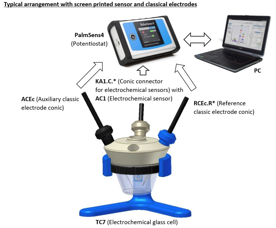
PalmSens4
Read moreThe PalmSens4, is a USB and battery powered Potentiostat, Galvanostat, and optional a Frequency Response Analyser (FRA) for Electrochemical Impedance Spectroscopy (EIS).
Compact, versatile and powerful
- (Bi)Potentiostat / Galvanostat / Impedance Analyzer
- FRA / EIS: 10 μHz up to 1 MHz
- 9 current ranges: 100 pA to 10 mA
- 18-bit resolution
- Bluetooth or USB connection
The PalmSens4 has a large potential range (-5V to 5V or -10V to 10V) and current range (100 pA to 10 mA) with a high resolution and low noise. The economical PalmSens4 is a complete laboratory instrument but its compact and rugged design makes it also ideal for field work.
Connecting via Bluetooth guarantees a perfectly floating measurement.
More information can be found through the link: https://www.palmsens.com/product/palmsens4/
Configurable
PalmSens4 comes in different configurations:
- ±5 V or ±10 V potential range
- EIS/FRA with maximum frequency of 100 kHz or 1 MHz
- optional BiPotentiostat module for second WE
- optional iR-Compensation
Standard included
- Rugged carrying case
- High quality, double shielded cell cable with
2 mm banana connectors for Working, Counter, Reference electrode and Ground - Crocodile clips
- Dummy cell
- USB cable
- Manual and Quick Start document
- PSTrace software for Windows
-
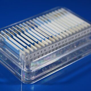
STK Starting kit
Read moreStarting kit STK.S
Set of twenty electrochemical sensors with a simple connector to find the best one to fit your application.
Starting kit is the set of twenty different electrochemical sensors to find the best one to fit your application. Starting kit contains 10 types of electrochemical sensors (2 sensors of each type), simple sensors connector and sensors box with numbered positions and silica gel.
Related products
-

Membrane Capacitive Deionization configurable cell (redox.me)
Read moreMembrane Capacitive Deionization (MCDI) configurable cell has been designed to conduct research on removal of charged ionic species from aqueous or organic solutions (i.e., Desalination/Demineralization) via electrostatic (i.e., non-Faradaic) or electrochemical (redox) interactions. The MCDI cell contains two graphite current collectors that can serve as polarization electrodes. However, if the electrode material is the subject of research, it should be applied to an additional current collector, such as graphite paper or metal felt (not included in the product). Different electrode materials can be installed on both sides of the cell. If the thickness of these electrodes exceeds 250 micrometers, different gaskets are required. In such a case, please contact us for a solution.
The cell is designed in such a way that replacing the electrodes does not require removing the membranes or flow fields. It is enough to unscrew the plungers on both sides and replace the electrodes. In the standard configuration, the liquid in the main channel and side channels flows through the flow field cut from PEEK. However, these can be replaced with a porous material such as felt or a battery spacer, which will allow fluid flow. If work with materials of dimensions different from those listed in the specification is required, we can supply seals of different thicknesses or customize the cell. The cell allows for the installation of one or two ion-exchange membranes (not included in the setup). Their thickness is not critical, and it is not necessary to adjust the thickness of the membrane gaskets pressing them. The cell elements are constructed with inert materials to the sample (PEEK). It well fits aqueous (FKM gaskets and O-rings) and organic solvent (FFKM gaskets and O-rings) electrolyte requirements. The construction of the cell is gas-tight.
Application note:
MCDI cell can be configured to allow the following cell architectures:- Flow-by CDI consisting of: (i) two porous carbon or metal based current collectors coated with capacitive (e. non-Faradaic) material, and (ii) a main flow field enabling the feed water to be transported between electrodes. In this configuration, side flow fields and membranes are not installed.
- Membrane CDI consisting of: (i) two porous carbon or metal based current collectors coated with capacitive (e. non-Faradaic) material, (ii) two ion-exchange membranes (cation exchange membrane and anion exchange membrane) separating electrodes from the main flow field, and (iii) a main flow field enabling the feed water to be transported between electrodes. In this configuration, side flow fields are typically not installed. However, there are cases where installing both side flow fields is justified. All the graphics included in the product page refer to that configuration.
- Inverted CDI consisting of: (i) two porous carbon or metal based current collectors coated with capacitive (e. non-Faradaic) material where anode is treated for net negative surface charge and a cathode is treated for net positive surface charge, and (ii) a main flow field enabling the feed water to be transported between electrodes. In this configuration, side flow fields and membranes are not installed.
- Flow-electrode CDI consisting of: (i) two porous carbon or metal based current collectors with flowing electrodes made of capacitive (e. non-Faradaic) carbon suspension, (ii) two ion-exchange membranes (cation exchange membrane and anion exchange membrane) separating electrodes from the flow chamber, (iii) a main flow field enabling the feed water to be transported between electrodes, and (iv) two side flow fields for liquid electrodes. All the graphics included in the product page refer to that configuration.
- Hybrid CDI consisting of: (i) a Faradaic (e. battery) electrode for cation adsorption/desorption, (ii) a capacitive (i.e. non-Faradaic) electrode for anion adsorption/desorption, (iii) an anion exchange membrane placed adjacent to the capacitive electrode, and (iv) a main flow field enabling the feed water to be transported between electrodes. In this configuration, side flow fields and a cation-exchange membrane are not installed.
- Cation intercalation desalination consisting of: (i) two porous carbon or metal based current collectors coated with Faradaic cation intercalation materials, (ii) an anion exchange membrane separating electrodes, and (iii) a main flow field enabling the feed water to be transported between electrodes. In this configuration, one side flow field and cation-exchange membrane are not installed.
- Desalination battery consisting of: (i) two porous carbon or metal based current collectors coated with redox (e. Faradaic) material (one for cation adsorption/desorption and the other for anion adsorption/desorption), and (ii) a main flow field enabling the feed water to be transported between electrodes. In this configuration, side flow fields and membranes are not installed.
Specification:
tubing size: 4 mm OD
fitting type: push-in, M5 male
electrode size: 60 mm x 60 mm (36 cm2)
recommended total electrode thickness: 200-250 µm
membrane size: 70 mm x 85 mm
maximum operating pressure: 20 bar
maximum operating temperature 150 ºCIntrastat data:
HS Code: 90278080
Country of Origin: Sweden
NET weight: 1300 gProduct includes:
2 x stand, anodized aluminum
2 x plunger holder, SS 316L
2 x PEEK plunger
2 x tantalum current collector
2 x graphite current collector
1 x threaded end plate, SS 316L
1 x unthreaded end plate, SS 316L
1 x PEEK outer cell body
1 x PEEK inner cell body
1 x set of fittings
2 x female banana connectors, 4 mm dia.
1 x PEEK main flow field, 0.5 mm thick
2 x PEEK side flow field, 0.5 mm thick
1 x set of gaskets (FKM or FFKM) including:1 x main flow gasket, 0.5 mm thick
2 x membrane gasket, 0.25 mm thick
2 x side flow gasket, 0.5 mm thick
2 x electrode gasket, 0.25 mm thick -

Raman Electrochemical Flow Cell, active area: 3.5 cm2, volume: 4.5 mL (redox.me)
Read moreThis cell combines two classical analytical techniques such as electrochemistry and Raman spectroscopy, to obtain in-situ chemical information about the reactions taking place during an electrochemical experiment. It consists mainly of three elements: (i) sample holder with Tantalum (formerly Copper) foil serving as an electric contact to working electrode surface, (ii) chamber in which reference and counter electrodes are installed together with electrolyte inlet and outlet and (iii) lid which seals the cell and holds the Sapphire window. The sample consisting of a thin film of electrochemically active material deposited on a rigid or flexible substrate (working electrode) is loaded from the bottom via magnetic or screw mount. The counter or/and reference electrodes are mounted in a top casing (either 2-, or 3-electrode setup. The oval counter electrode made of e.g. Platinum wire assures uniform distribution of the field lines along the path to working electrode. During an experiment Raman laser is focused onto the surface of a thin film working electrode through a transparent Sapphire window and thin layer of electrolyte (total optical path of 3.25 mm). The electrolyte thickness of 2.25 mm ensures free diffusion of ions (e.g. protons) and its counter ions.
The electrode adapter for installing 6 mm dia. electrodes inside Raman ECFC is available here. It enables using disk electrode, plug with clip or any other rod-shape electrode (e.g. graphite rod) or current collector (e.g. metal mesh, graphite coated metal mesh, metal foil, graphite coated metal foil, metal foam, carbon woven and non-woven fabrics, carbon paper, etc.) as working electrode instead of a flat electrode in default Raman ECFC configuration.
The screw mount variant of Raman ECFC can be converted into GDE Raman ECFC by using Gas Compartment. This conversion allows installation of Gas Diffusion Electrodes as working electrode.
The cell elements are constructed with materials that are inert to the sample (PEEK, Fluorocarbons). It well fits aqueous (FKM O-Rings) and organic solvent (FFKM O-Rings) electrolyte requirements. The construction is gas-tight and can be used when the removal and exclusion of contaminants such as oxygen and water is required by bubbling of an inert gas through the electrolyte (in an external reservoir).
Application note:
This cell can be used to track kinetic phenomena such as the near-surface proton concentration changes during oxidation and reduction reaction at working electrode. It can be also used to identify materials such as carbon, metal oxides, polymers and electrolytes, and to determine their structure and distribution. Various metals are suitable for this cell as auxiliary electrode including Platinum, Gold and Silver.Specification:
nominal exposure area: 3.5 cm2
electrolyte volume: 4.5 mL
optical path (including Sapphire window): 3.25 mm
electrode plug diameter: 6 mmIntrastat data:
HS Code: 90275000
Country of Origin: Sweden
NET weight: 200 gProduct includes:
1 x chamber
1 x Reference electrode (Ag/AgCl, or Ag/Ag+), 30mm
1 x Metal wire auxiliary electrode – ST 0.6/150 mm, Platinum
1 x Sapphire window – 0054PSPCM
1 x lid
1 x WE Tantalum contact
1 x sample holder
1 x plug – 0005CPEMA -
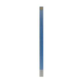
AC3 Electrochemical sensor
Read moreNarrow amperometric single working electrode sensor made by thick film technology
Dimensions: 50.8 x 2.54 x 0.63 mm
WE material: Au/Pt, Au, Pt, Ag, C
The sensor is formed on a corundum ceramic base. On to this surface the working electrode is applied. The working electrode is made of variety of materials. At the end of the sensor there is a contact which is connected with the active part by the silver conducting paths which are covered by a dielectric protection layer. A bio-chemically active substance can be immobilised on the working electrode of the sensor.
-

Front contact photo-electrochemical H-Cell setup (redox.me)
Read moreThis is a horizontally mounted, double compartment photo-electrochemical H-Cell used to simultaneously or individually investigate thin film photo-anode and photo-cathode. The cell elements are made of PEEK and Fluoropolymers. It well fits aqueous (FKM O-Rings) and organic solvent (FFKM O-Rings) electrolyte requirements. The construction is gas-tight having two separate chambers, each equipped with gas inlet and outlet. This allows bubbling the solution and evacuating gases. Chambers are separated with an ion-exchange membrane (e.g., DuPont’s Nafion® membrane), so the electrochemical products appearing at photo-anode and (photo-)cathode do not affect the opposite electrode.
Application note:
This cell allows several approaches to perform measurements in 2- or 3-electrode setups. It is designed to investigate performance of a thin film photo-anode or photo-cathode (e.g. nanocrystalline material or conducting polymer) deposited on a rigid or flexible transparent substrate (typically fused quartz glass). The counter electrode is mounted in the second chamber either in a top casing or attached on the side of the cell as a thin film deposited on rigid or flexible substrate. The reference electrode is mounted in a top casing of the same chamber as the studied photo-electrode. Various auxiliary electrodes are suitable for this cell including metal wire, gauze and foil electrodes as well as non-metal electrodes and thin films. Typical applications include: basic photochemistry (photo-catalysis), photolytic water splitting, photoinduced charge separation and photo-corrosion.Specification:
minimum electrolyte volume: 2×10 mL
maximum electrolyte volume: 2×15 mL
electrode plug diameter: 6 mm
maximum substrate thickness: 3 mmIntrastat data:
HS Code: 90309000
Country of Origin: Sweden
NET weight: 600gSetup includes:
1 x Front Contact Photo-Electrochemical H-Cell
2 x lid – 0001CPEMA
2 x chamber
2 x sample mount
2 x Tantalum contacts
1 x micro tripod
4 x plug
1 x set of O-Rings (18 pcs)
1 x Metal Wire Auxiliary Electrode – 50HX15 0.6/250 mm (Platinum)
2 x Reference electrode (Ag/AgCl, or Ag/Ag+), 30 mm