


ZIVE SP3 – potentiostat/galvanostat/impedance analyzer
- Research grade potentiostat/galvanostat/impedance analyzer
- Control voltage range: ±10V, ±1V, ±100mV
- Control current range: 2nA ~ 2A (2nA with gain, 10 ranges)
Application
- Battery/Super capacitor
- Fuel cell
- Coating
- Corrosion
- Sensor
- Solar cell
- Other Echem experiments
Features
- high compliance voltage potentiostat/galvanostat/impedance analyzer
- ±10V@2Amp control range
- current range (10 ranges)
– 2A to 20nA
– 2nA with gain - frequency range : 10uHz ~ 1MHz
- 14 EIS techniques capability including multisine
- Electrical isolation floating potentiostat can be used with autoclaves, mechanical stress apparatus, or pipeline probes.
- suitable for typical corrosion applications
– pitting, crevice corrosion, and passivation behavior
– corrosion rate (Tafel Plot) determination
– active/passive characteristics
– passivation rates
– anodic and cathodic protection - high speed data sampling time
– 2usec or 3usec depending on data point number - fast sweep mode (5000V/sec with 10mV data sampling)
- iR compensation & measurement
- 3 measurement/control voltage ranges &
10 measurement/control current ranges - internal 542,000 data point storage & continuing experiment regardless of PC failure
- LCD display
- software package
– Corrosion software package(COR3)
– EIS software package
– Electrochemical analysis software package
– Energy software package - multichannel configuration available by connecting multiple SP3 or other ZIVE products
- included basic software, Energy(battery)/Impedance/Corrosion/Echem analysis software packages
- free software upgrade
Experimental Techniques
Basic techniques
- Potentiostatic
- Galvanostatic
- Double step potentiostatic
- Double step galvanostatic
- OCP measurement
- Potential sweep
- Current sweep
- Cyclic voltammetry
- Fast potential sweep
- Potentiostatic Ru measurement
- Galvanostatic Ru measurement
Advanced software techniques (Included)
Options
- Power booster
| Power amplifier (CE) | |
| Power | 40Watt(20V@2A) |
| Compliance voltage | ±20V |
| Max. current | ±2A |
| Control speed selection | 4ea |
| Bandwidth | 1MHz |
| Slew rate | 8V/usec |
| Potentiostat mode(voltage control) | |
| Voltage control | |
| – Control voltage range | ±10, ±1V, ±100mV |
| – Voltage resolution | 16 bit per each range |
| – Voltage accuracy | ±0.02% fs (gain x1) |
| – Max. scan range | ±10V vs. ref. E |
| Current measurements | |
| – Current range | 10 ranges (auto/manual setting) 2nA~2A (2nA with gain) |
| – Current resolution | 16 bit 60uA, 6uA, 600nA, 60nA, 6nA, 600pA 60pA, 6pA, 600fA, 60fA |
| – Current accuracy | ±0.03% f.s.(gain x1)>200nA |
| Galvanostat mode(current control) | |
| Current control | |
| – Control current range | max. ±2A ± full sacle depending on selected range |
| – Current resolution | 16 bit 60uA, 6uA, 600nA, 60nA, 6nA, 600pA 60pA, 6pA, 600fA, 60fA |
| – Current accuracy | ±0.03% f.s.(gain x1)>200nA |
| Voltage measurements | |
| – Voltage range | ±10V, ±1V, ±100mV |
| – Voltage resolution | 16 bit; 0.3mV, 30uV, 3uV |
| – Voltage accuracy | ±0.02% fs(gain x1) |
| Electrometer | |
| Max. input voltage | ±10V |
| Input impedance | >2×10¹³Ω||4.5pF |
| Bandwidth | >22MHz |
| CMRR | >114dB |
| EIS Measurement for system | |
| Frequency range | 10uHz ~ 1MHz |
| Frequency accuracy | <0.01%> |
| Frequency resolution | 5000/decade |
| Amplitude | 0.5mV ~ 5Vrms(potentiostatic) 0.1 ~ 70% f.s.(galvanostatic) |
| Mode | Static EIS: potentiostatic, galvanostatic, pseudo-galvanostatic, OCP Dynamic EIS: potentiodynamic, galvanodynamic Fixed frequency impedance: potentiostatic, galvanostatic, potentiodynamic, galvanodynamic Multisine EIS: potentiostatic, galvanostatic Intermittent PEIS/GEIS |
| Main system | |
| PC communication | USB2.0 high speed |
| Line voltage | 100~240VAC, 50/60Hz |
| Size/weight | 195x313x105mm(WxDxH) |
| LED indicator | Run, Comm |
| Max. output power | 40Watt |
| Software | |
| Max. steps per experiments | 1,000 |
| Shutdown safety limits | voltage, current, temperature etc. |
| Max. sampling rate | 2usec or 3usec depending on data point number |
| Min. sampling time | unlimited |
| Sampling condition | time, dv/dt, dI/dt, temp. etc. |
| Interface for system | |
| Auxiliary port | |
| – Digital output | 3 (open collector) |
| – Digital input | 1 (photo coupler) |
| – Auxiliary voltage inputs | 3 analog input: ±10V for measurement of WE vs. CE CE vs. RE or other signal |
| – Analog output | 1 analog output : ±10V for stirrer, MFC, RDE etc. |
| Misc.port | |
| – Peripheralcommunication | I2C to control exte al devices |
| – Temperature measurement | 1 K-type thermocouple input |
| – Zero resistance ammeter | 20nA ~ 2A ranges |
| System | |
| Cell cable | 1 meter shielded type (standard) working, reference, counter, working sense |
| Calibration | Automatic |
| Control DAC |
DSP with FPGA 2x16bit DAC(50MHz) for bias & scan 1x16bit DAC(1MHz) for analog output |
| Dataacquisition ADC |
2x16bit ADCs(500kHz) for voltage & current 4x16bit ADCs(250kHz) for auxiliary voltage and temperature reading |
| Calibration | Automatic |
| Filter selection | 4ea(5Hz, 1kHz, 500kHz, 5MHz) |
| Scan rate | 0 ~ 200V/sec in common mode 0 ~ 5000V/sec in fast mode |
| Inte al data memory | 542,000 points |
| LCD display | DC & EIS mode automatically |
| PC requirement | |
| Operating system | Windows 7/8/10(32bit/64bit OS) |
| PC specification(minimum) | Pentium4, RAM 1GB or higher |
| Display | 1600×900 high color or higher |
| USB | high speed 2.0 |
| General | |
| Dummy cell | One exte al dummy cell included |
| Thermocouple | 1.5meter K-type (option) |
| Auxiliary cable | Option |
| Misc. cable | Option |
| Impedance data analysis software | ZMANTM software |
| DC data analysis software | IVMANTM software |
The specifications are subject to change without notice.
Related products
-
USB Potentiostat Galvanoplot
Read moreUSB Potentiostat Galvanoplot is a super small, low-cost and affordable device suitable for dedicated volume applications, which is optimized for screen-printed sensor and biosensor applications. It can be used in many other research areas and with other electrochemical sensors, for corrosion measurement, battery and super-capacitors or fuel cells.
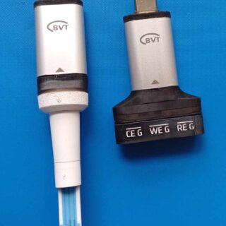
It is capable of performing all common Amperometric and Voltammetric electrochemistry protocols (CA, LSV, CV, DPV, NPV, SVW, GAL) and can be used with three electrode (WE/RE/CE) and two electrode (WE/RE-CE) setups. Plug the device directly into an Android mobile device through OTG port for a true on-site analysis experience. It is possible to choose from two types of interfaces allowing direct insertion of the BVT SPE sensors or the use of 3 classical electrodes with 2 mm banana plugs (WE, RE, CE).
- Dimensions: 39x17x8 mm
- Weight: 5 g without sensor interface
- Voltage scan range: +-3V @1mV resolution
- Max current: 2000 nA (*at the request of the customer, it is possible to change the range, but this will change the resolution, noise and other parameters)
- Current resolution: 300pA@1KSPS/ 100pA@100SPS/ 30pA/10 SPS resolution
- Noise around: 50nA@1KSPS/ 7nA@100SPS/ 400pA/10 SPS
- Protocols: CA, LSV, CV, DPV, NPV, SVW, GAL
- Cell type: WE/RE/CE and WE/RE-CE
Connectivity: USB-C (Plug the device directly into an Android mobile device through OTG port for a true on-site analysis experience)
- Operating system compatibility: Windows 8, 10+
- Advanced analysis – filtering and auto peaks
Device Usage
- Electrochemical measurements
- Measurements with biosensors and electrochemical sensors
- Measurement of biochemical activity of a sample
- Corrosion measurement
-

Basic Sample Holder – metal contact, 4 mm max. thickness (redox.me)
Read moreBasic Sample Holder with a metal contact works as an electrical conductor between an electrode material (free-standing or deposited on a substrate) and an external circuit. This holder consists of PEEK body, pure Tantalum, Stainless Steel 316L, Titanium, Copper or Nickel metal electrical contact, and PEEK screw to fix the electrode. It is compatible with most of inorganic and organic based plates, free-standing membranes or thin films deposited on flexible and rigid substrates. A maximum thickness of the sample is 4 mm. Tantalum is known to be inert to practically all organic and inorganic compounds. Tantalum’s corrosion resistance is very similar to that of glass, as both are unsuitable for use in hydrofluoric acid and strong hot alkali applications. Therefore, in those cases, we recommend the other wire contact variant. The metal contact can be fully immersed in the electrolyte.
Application note
Generally, the electrode is fabricated by fixing the electrochemical active sample into the holder using a screw. Such electrode is immersed in the ion-conducting solution as a working electrode or counter electrode. An electric current is passed between the working electrode and the counter electrode for a certain amount of time. Metal wire contact is permanently installed in the PEEK body. The holder is designed to be used multiple times. The holder should be cleaned prior to the installation of electrode material.Specification
holder body material: PEEK
rod diameter: 6 mm
contact material: Ta, SS 316L, Ti, Cu or Ni
contact wire diameter: 0.6 mm
contact wire total length: 110 mm
holder length: 70 mm
maximum sample thickness: 4 mmIntrastat data
HS Code: 90309000
Country of Origin: Sweden
NET weight: 100 gProduct includes
1 x Basic Sample Holder
1 x PEEK M3 screw
1 O-Ring (FKM for aqueous or FFKM for organic electrolytes) -

ZIVE SP2 – high quality potentiostat/galvanostat/impedance analyzer
Read more- Versatile high quality potentiostat/galvanostat/impedance analyzer
- Control voltage range: ±10V, ±1V, ±100mV
- Control current range: 200pA ~ 2A (200pA with gain, 11 ranges)
Application - Battery/Super capacitor
- Fuel cell
- Corrosion
- Sensor
- Solar cell
- Other Echem experiments
Features
- high quality potentiostat/galvanostat/impedance analyzer
- ±10V@2Amp control range
- current range (11 ranges)
– 2A to 200pA
– 200pA with gain - frequency range : 10uHz ~ 2MHz
- built-in FRA : enables EIS tests
- 14 EIS techniques capability including multisine
- capable of multitude of applications
– corrosion, general electrochemistry, sensor, battery, fuel cell,
supercapacitor, solar cell, etc. - bipolar pulse capability
- voltage pulse or current pulse charge/discharge test(GSM,CDMA etc.),
sine wave function for ripple simulation in battery test package
& pulse plating available - high speed data sampling time
– 2usec or 3usec depending on data point number - fast sweep mode(5000V/sec with 10mV data sampling)
- iR compensation & measurement
- 3 measurement/control voltage ranges &
11 measurement/control current ranges - internal 542,000 data point storage & continuing experiment regardless
of PC failure. - LCD display
- software package
– Corrosion software package
– EIS software package
– Electrochemical analysis software package
– Energy software package - multichannel configuration available by connecting multiple SP2 or other ZIVE products
- power booster(ZIVE ZB series) available
- inclues basic software, Energy(battery)/Impedance/Corrosion/Echem analysis software packages
- free software upgrade
Experimental Techniques
Basic techniques
- Potentiostatic
- Galvanostatic
- Double step potentiostatic
- Double step galvanostatic
- OCP measurement
- Potential sweep
- Current sweep
- Cyclic voltammetry
- Fast potential sweep
- Potentiostatic Ru measurement
- Galvanostatic Ru measurement
Advanced software techniques(Included)
- EIS software package(EIS)
– Potentiostat EIS
– Galvanostatic EIS
– Pseudo galvanostatic EIS
– OCP* EIS
– Potentiodynamic PEIS
– Galvanodynamic GEIS
– Poteniodynamic HFR
– Galvanodynamic HFR
– Galvanostatic HFR monitor
– Potentiostatic HFR monitor
– Multisine potentiostatic EIS
– Multisine galvanostatic EIS
– Intermittent potentiostatic EIS
– Intermittent galvanostatic EIS
(*) The system measures open circuit potential before each frequency
change and applies AC sine wave on this potential. - Corrosion software package(COR)
– Tafel(Tafel experiment)
– Rp(Polarization resistance)
– RpEc trend
– PDYN(Potentiodynamic)
– CYPOL(Cyclic polarization resistance)
– GDYN(GalvanoDynamic)
– Reactivation
– Galvanic corrosion
– Potentiostatic ECN
– Galvanostatic ECN
– ZRA mode ECN - Energy software package(BAT)
a) Battery test technique
– CC/CV testforcycle life test of lithium battery
– CC/CC tet forcyclelifetestofNiCd or NiMH battery
– Discharging test
– EVS(electrochemical voltage spectroscopy)
– Variable scan rate CV
– Potentiostatic IV curve
– Galvanostatic IV curve
– Steady state CV
– PITT(Potentiostatic intermittent titration technique) test
– GITT(Galvanostatic intermittent titration technique) test
– Pulse mode is available for GSM & CDMA profile.
Pulse shape profile can be measured by user’s demand.
b) Control mode
– Charge : CC, CC-CV, pulse, sine wave
– Discharge : CC, CP, CR, pulse, sine wave
c) Cut-off condition
– Time, voltage, current, power, auxV etc.
– Various battery charge/discharge test is available including
pulse discharge for GSM, CDMA application - Electrochemical analysis software package(EAS)
a) Step techniques
– CA(Chronoamperometry)
– CC(Chronocoulometry)
– CP(Chronopotentiometry)
b) Sweep techniques
– LSV(Linear sweep voltammetry)
– SDV(Sampled DC voltammetry)
– Fast CV
– Fast LSV
c) Pulsed techniques
– DPV(Differential pulse voltammetry)
– SWV(Square wave voltammetry)
– DPA(Diff.pulse amperometry)
– NPV(Normal pulse voltammetry)
– RNPV(Reverse normal pulse voltammetry)
– DNPV(Differential normal pulse voltammetry)
Options
- Power booster
-

Sample Holder 25 mm x 25 mm (redox.me)
Read moreThe sample holder (known also as flat specimen holder) is used for holding flat, circular or square/rectangular samples. It enables contacting the sample from the front (e.g. ITO/FTO glass, Monolayer Graphene on SiC, or Boron-Doped Diamond thin film on various substrates) and from the back (e.g. metal specimen, Glassy Carbon plate, Boron-Doped Diamond plate). The default nominal aperture is 1cm2, but other value can be provided on request. The large electrical contact with Tantalum (formerly Copper) foil surface (not being in contact with an electrolyte) ensures optimal current collection by minimizing electrical resistance and unifying current distribution. The rod with electrical connection has a diameter of 6 mm, which makes the sample holder compatible with our voltammetry cells and jacketed cells, as long as it fits in. We may also provide an adapter to install this sample holder in openings larger than 6 mm dia.
The sample holder elements are constructed with materials that are inert to the electrochemical system (PEEK, Fluorocarbons). It well fits aqueous (FKM/EPDM O-Rings) and organic solvent (FFKM O-Rings) electrolyte requirements. The construction is well sealed which prevents the electrolyte to leak inside.
Application note
The sample holder is used largely for corrosion studies. It can be installed in a beaker type cell as well as in testing environments such as open water reservoirs, cans, tanks etc. It can also be used wherever it is necessary to make an electrode using a thin layer of an active material deposited on a flat substrate (conducting or insulating).Specification
nominal aperture range: 0.008 cm2 (1 mm dia.) – 4.155 cm2 (23 mm dia.)
minimum aperture: 0.008 cm2 (1 mm dia.)
maximum aperture: 4.9 cm2 (23 mm dia.)
electrical connection diameter (rod): 6 mm
minimum substrate size:nominal aperture minimum substrate size 0.008 cm2 (1 mm dia.) 10 x 10 mm2 (square) or 12 mm dia. (circular). 0.196 cm2 (5 mm dia.) 7 x 7 mm2 (square) or 10 mm dia. (circular). 0.283 cm2 (6 mm dia.) 8 x 8 mm2 (square) or 11 mm dia. (circular). 0.385 cm2 (7 mm dia.) 9 x 9 mm2 (square) or 12 mm dia. (circular). 1 cm2 (11.3 mm dia.) 13 x 13 mm2 (square) or 16 mm dia. (circular). 1.76 cm2 (15 mm dia.) 17 x 17 mm2 (square) or 20 mm dia. (circular). 3 cm2 (19.5 mm dia.) 22 x 22 mm2 (square) or 24 mm dia. (circular). 3.5 cm2 (21 mm dia.) 23 x 23 mm2 (square) or 25 mm dia. (circular). 4.155 cm2 (23 mm dia.) 25 x 25 mm2 (square only) maximum substrate size: 25 x 25 mm2
maximum sample thickness: 4 mm
contact type: front or backIntrastat data
HS Code: 90309000
Country of Origin: Sweden
NET weight: 100 gProduct includes
1 x chamber
1 x lid
1 x contact (Tantalum foil)
1 x rod with electrical connection